FreDA – Portable Device for Frequency Domain Analysis of HV Equipment Insulation and Power Transformer Winding
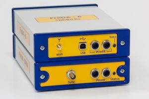
The FreDA (Frequency Domain Analyzer) portable device is used for high-voltage equipment winding geometry monitoring in a wide frequency range.
It allows finding transformer winding deformations by SFRA (Sweep Frequency Response Analyzer) Test.
Frequency parameter measurement by SFRA Test allows detecting winding geometry distortion arising during operation.
This dangerous defect, leading to deformation of the insulation gaps in the winding, occurs in power transformers under two interrelated conditions: when the winding clamping weakens and as a result of large short-circuit currents flow through the transformer windings.
For winging deformation detection, an alternating voltage and frequency generator is integrated into the FreDA device.
The frequency slowly varies in the range from 2.0 Hz to 20.0 MHz it is necessary to keep in mind, that winding frequency parameter measuring at 5 kHz and less is not informative, as the core remaining magnetization influence is considerable. The same concerns measuring at 2 MHz and higher.
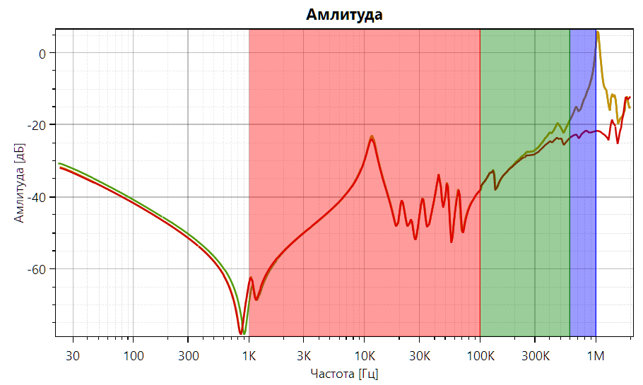
For winding geometry monitoring the dependence of the complex signal attenuation factor to the applied voltage frequency is measured for each phase. The measured frequency dependences are compared to each other. If the difference in amplitude or signal attenuation phase is found in the narrow frequency range, then it is a sign of winding deformation.
If the reference (original) coefficient of attenuation factor to frequency is given by the transformer manufacture, then the analysis could be more precise.
The FreDA Device Design
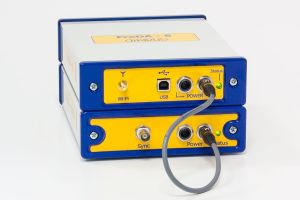
The device consists of the two modules: the measuring module and the power supply module with the batteries. The modules are connected with a short cable.
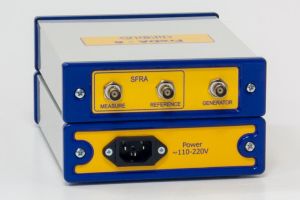
In the back panel of the device there are three slots:
- SFRA measuring channel input
- SFRA reference channel input
- Generator output
All the grounding cables and the measuring cables and clamps are supplied together with the device.
The device control is done from a lap-top and software which runs under Windows. The software is supplied together with the device free of charge. The software includes the connection diagrams according to IEEE Std C57.149-2012 «IEEE Guide for the Application and Interpretation of Frequency Response Analysis for Oil-Immersed Transformers».
Analysis According to DL/T 911-2016 Standard
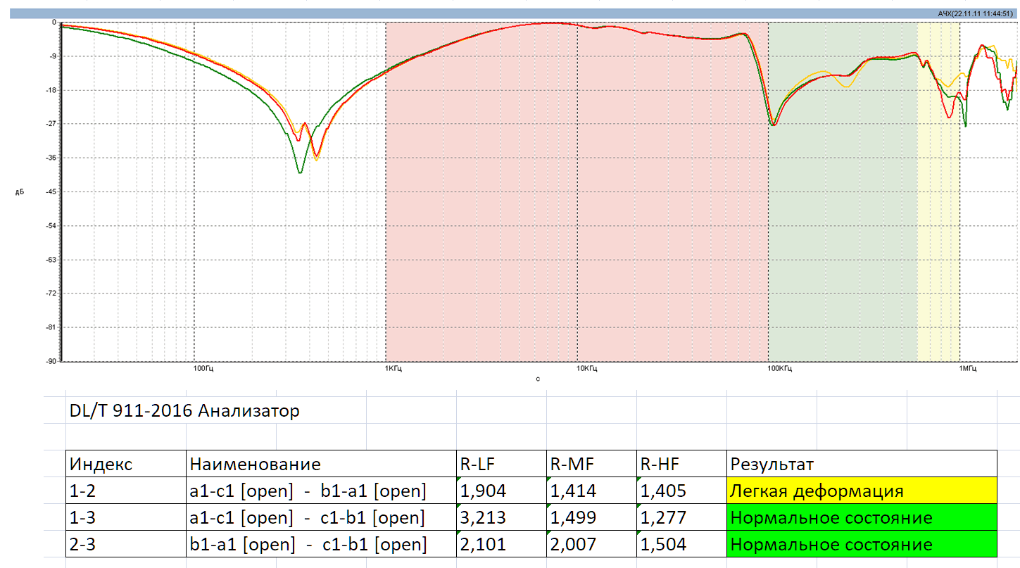
In the software the correlation analysis method is used. The PRPD of different phases are compared to each other. If there are PRPDs received for the equipment being tested earlier, then the comparative analysis is made. Also the comparison can be made to the data given by similar equipment.
During the expert review for defect revelation the calculation method is use based on the electric power industry standard of P.R.C. – DL/T 911-2016. The analysis calculates R correlation coefficients in three frequency rangers.
Additional Recomendations
- International Standard IEC 60076-18(2012). Power transformers – Part 18: Measurement of frequency response
- CIGRE Working Group A2.26, Brochure 342 Mechanical Condition Assessment of Transformer Windings using Frequency Response Analysis (FRA)
- CIGRE Working Group A2.53, Brochure 812. Advances in the interpretation of transformer Frequency Response Analysis (FRA). September 2020
- IEEE Std C57.149™-2012 IEEE Guide for the Application and Interpretation of Frequency Response Analysis for Oil-Immersed Transformers
- DL/T 911-2016 standard. Frequency response analysis on winding deformation of power transformers (PRC)
Specifications of «FreDA» device
| Frequency range for winding geometry monitoring, MHz | 0,000002 ÷ 20,0 |
| Inbuilt generator output voltage, range, Volts | 1 ÷ 10 |
| Measured signal dynamic range, dB | 120 |
| Operation from battery, hours | 4 |
| Dimensions of measuring device, mm | 230 х 150 х 100 |


