Ganimed – Multipurpose Device for HV Transformers OLTC Testing

One of the most critical parameters which determine power supply quality is maintaining the voltage level.
The voltage level is controlled by the On Load Tap Changer (OLTC).
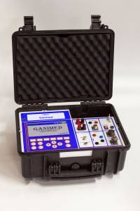
Multipurpose «Ganimed» device is for testing and reliability checking of high voltage power transformers OLTC contacts and joints.
«Ganimed» Device Functions
«Ganimed» device allows measuring and analyzing the standard OLTC parameters that are specified in the OLTC certificate by the manufacturer, such as contactor operation time diagram and OLTC selector circle diagram.
Additional «Ganimed» Device Functions
«Ganimed» device allows:
- Measuring transient resistance of the OLTC contacts by the inbuilt ohmmeter.
- Analyzing OLTC mechanical drive condition on the base of the electric motor consumed power graph (measured during one commutation cycle) and OLTC vibration graph (measured synchronically).
DRM Method

An important feature of «Ganimed» device is the hardware and firmware realization of the method known as Dynamic Resistance Measurement test (DRM-test). This is the only method which allows effective diagnostics of OLTC condition without opening the tank.

The circuit for «Ganimed» connection while using this method of OLTC diagnostics in presenter in the figure. In this circuit the secondary winding of the power transformer is shorted, and 1A or 2A direct current is passing through the primary winding. While the secondary winding is shorted, the power transformer acts as a measuring current transformer, and the magnitude of the primary current doesn't much influence the processes in the transformer core and winding.

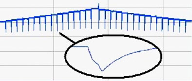
DRM-test is made in consecutive order for all the OLTC positions, in forward and backward directions of selector operation. The curve of the current change in the transformer primary winding is in the figure.
Also you can assess the contactor operating time by the switching current pulse waveform. In the figure one commutation with better resolution is shown in the oval.
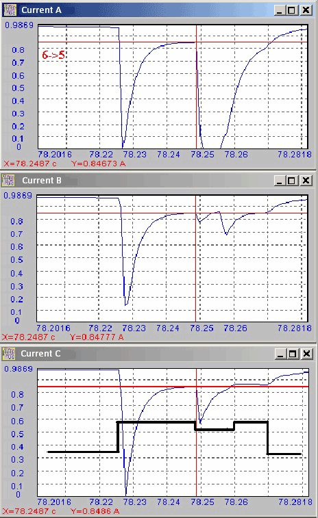
In the screenshots below there are of the oscillograms of OLTC operation at switching from «6» position to «5» position -the transformer has defects in the switcher.
For time orientation, in the third screenshot for «С» phase, there is also the oscillogram of contactor operation, made by the same device but another method.
The difference in the transients in different OLTC phases during commutation is evident from the graphs. These differences are caused by deterioration of contacts in «A» phase and changing the time phases of the contactor in «B» phase.
The presence of several complementary methods in one device allows the most effective diagnostics operation scheduling, while taking into account the actual characteristics of the equipment.
Diagnostics strategy will be based on the real features of equipment.
«Ganimed» Specifications
| Time resolution of OLTC oscillogram, ms | 1 |
| Maximal time of OLTC cycle diagram measurement, min | Up to 30 |
| DRM-test cycle (all positions), min | Up to 20 |
| OLTC tank vibration measurements during commutation, mm/s | 0.3 ÷ 100 |
| Device case dimensions, mm | 410*340*250 |


